Heading www.gapilot.co.uk

Build Diary 14/15/16-October-05


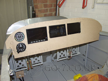
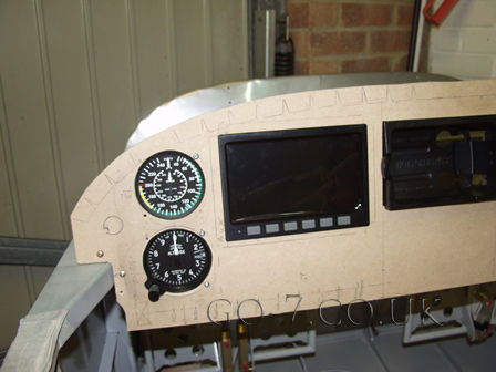
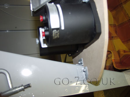
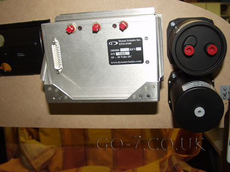
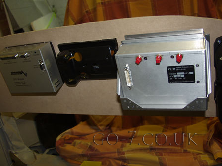
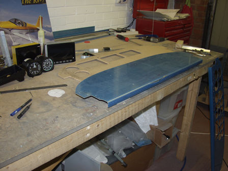
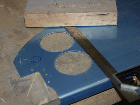
I decided to take a break from the empannage. As it's cold 
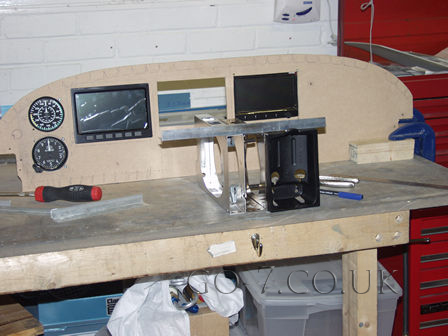
outside - so I decided to plan the instrument panel layout and make a (second) mockup in MDF.

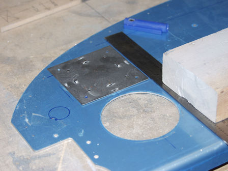
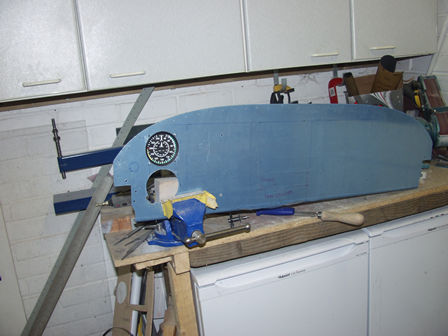
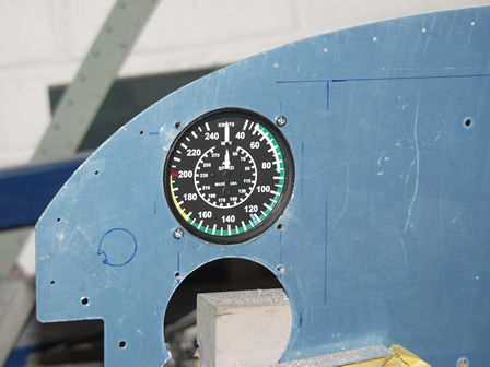
Sunday. I am pleased with the layout so decide to cut the instrument panel.

This is the second mockup of the instrument panel in MDF. As soon as I had cut the first one out and fitted the instruments I didn't like it. It just looked all wrong. I am pleased with this layout, the radio and transponder will go under the GPS. The switches and CB's will go left to right at the bottom of the panel.
On the first layout I had the Altimeter and ASI under the Dynon. I had tought about putting them in the center, but I want the radio and transponder in the center so the passenger can change the frequency (and transponder code) for me.
The design has the instruments as far over to the left of the panel as possible. As you can see in this picture the metal behind the instrument panel must be taken into account.
This is a good position - not too close.
With this layout the static and pitot are in one area.
The back of the panel. Dynon D100, Garmin 296 GPS holder and AF-2500.
Here I am planning the radio and transponder layout.
Radio and transponder holder.
Radio and transponder in position. The yellow tape on the Engine Monitor (AF-2500) is to stop dust and metal from entering through the air vents.
I have fitted a small spacer between the radio and transponder. You can just see it in this picture.
Time to cut the actual panel now....
First the Air Speed Indicator and Altimeter. The other making is for the ignition.
This is an instrument hole punch. It's reversable to cut the smaller instrument holes. The other half can be seen in the background.
The other half of the instrument hole cutter.
It took some pulling through. I resorted to my breaker bar for the last few turns - EASY!
The monent of truth! Will I have to re-order a new panel? NO, it went well and the holes are in alignment. Spot on!
Still not there yet. The four holes need to also be in align. This is an instrument hole fixing alignment template. The holes must be straight or the instrument will be crocked.
Here I have made the additional cut-out for the Altimeter - the lower hole.
The Air Speed Indicator fitted. The first instrument!

Images & text copyright GAPilot & Go-7. This mail is not connected to Vans Aircraft Inc. The contents of this site is the opinion of the author, not Vans Aircarft, PFA, CAA or FAA. Please check all information is correct before you act upon it.