Heading www.gapilot.co.uk

Build Diary 03/04-January-06

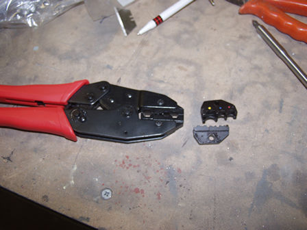
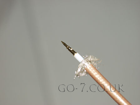
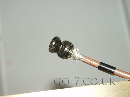
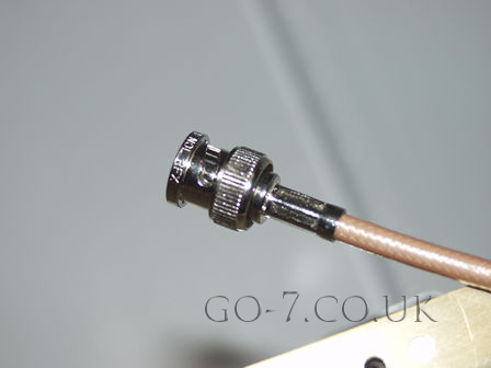
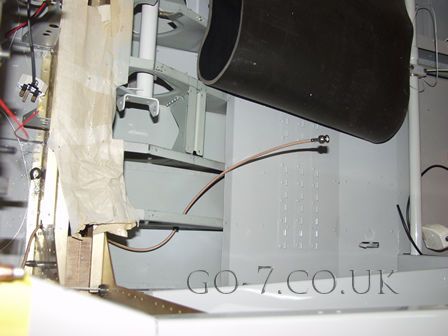
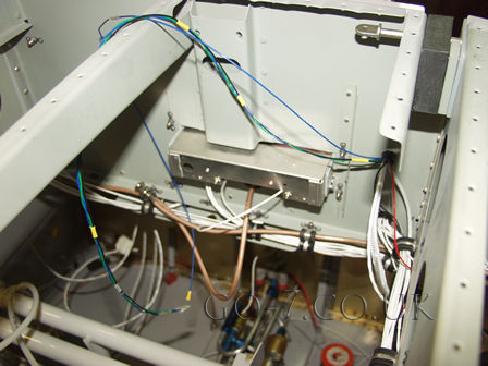
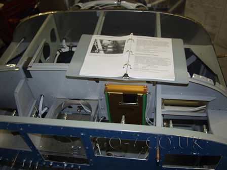
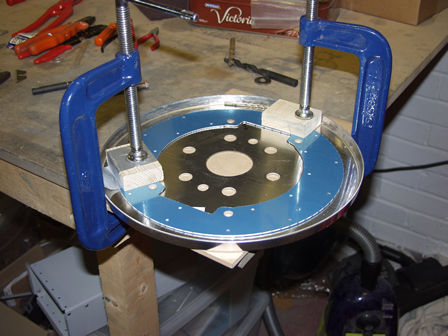
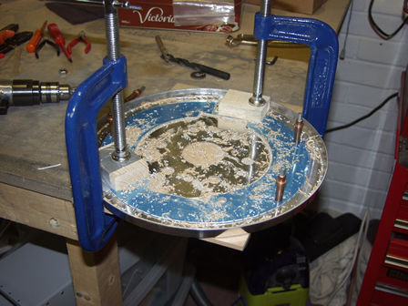
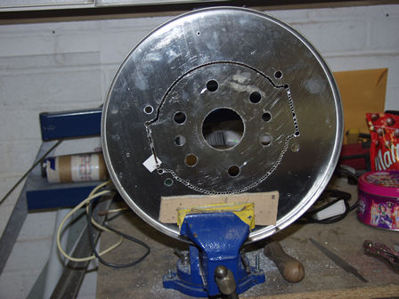
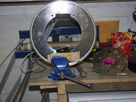
Connecting sensors to AF-2500. Fitting aerial leads for transponder and radio. Starting work on cowl - spinner, with the intention of fitting the spinner to align the cowl. BUT I discovered a problem with my plan. I am fitting a CS prop, the spinner fits to the prop. Rather than the plate fixing to the flywheel. I don't have my prop yet - so I can't fit the spinner thus I can't fit the cowl

These are my cable crimps. I bought these a few years ago in a kit with some automotive wire connections. I was purchasing - from a website in the US - some RG400 cable for the radio and transponder which needs BNC connectors fitting. The website had the cable crimps which looked just like mine, but obviously with different jaws - they also sold just the jaws! My dilemma was. In the UK the only crimpers I could find cost around £60-80. The site had them for $40 or just the jaws for $15 (about £8!). So do I buy the whole tool or save even more buy just the jaws. What if I then find the jaws don't fit my tool! Well tight me bought just the jaws, they fitted and did the job really well.
Fitting the BNC connector. Carefully cut outer plastic, pull back braded outer (very thick onthis RG400. Then trim center insulation to fit pin from BNC connector. Not forgetting to fit connector outer first.
After crimpint center pin push on outer part of connector until the center pin 'clicks' into place. Push brading back over connector and trim.
Slide over cable clamp and crimp.
This is the radio cable. The aerial will go in between the ribs where the cable comes out. Note I have kept the masking paper on the spar to tray and keep the gap clean.
Behind the radio and transponder. I am routing the aerial cables for the transponder and radio in oposite directions to ensure they do not interfere with each other.
Here I am starting to wire the AF-2500 Engine Monitor Analogue unit.
Crouched in the fuse wiring is hard work. So I decided to take a break and do the work needed on the spinner back plate This is the spinner back plate. I am fitting a constant speed unit so the back plate needs to be modified.
Hard to see but I have drilled pilot holes around the center.
The center part needs to be removed for the constant speed prop.
Center removed.

Images & text copyright GAPilot & Go-7. This mail is not connected to Vans Aircraft Inc. The contents of this site is the opinion of the author, not Vans Aircarft, PFA, CAA or FAA. Please check all information is correct before you act upon it.