Heading www.gapilot.co.uk

Build Diary 26/27-May-06

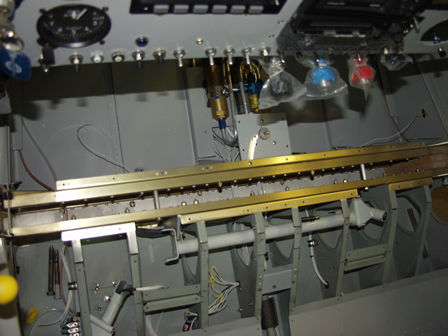
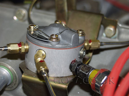
The connectors I have been waiting to arrive to connect the flap indicator (and warning lamps) arrived today. So I was able to complete the flap motor with indicator installation. Also wired in the starter warning lamp and the backup alternator warning lamp.

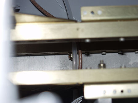
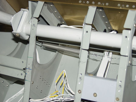
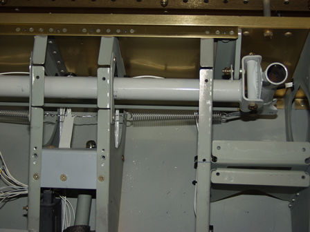
As I was inside the cockpit 
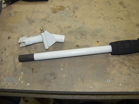
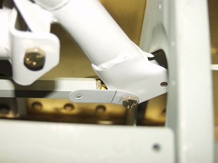
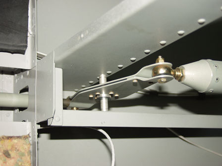
I decided it was time to complete the aileron trim installation, and connect the control stick together. 
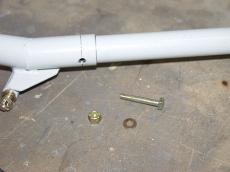
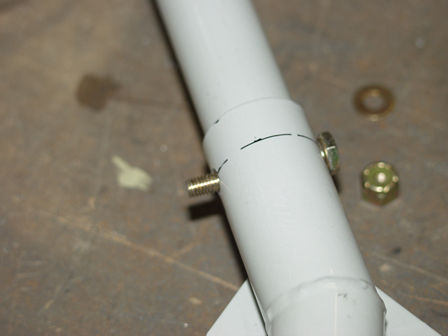
This was also prompted by an AD from the PFA (arriving this morning) regarding the provision of a solid fixing for the removable PAX stick.

Hard work and cramped, I had to keep getting out to streach my legs!

The PAX stick can be removed. However after a landing accident the PFA have issued a manditory notice to secure the PAX stick.
The manditory notice required a bolt to be fitted. I had already decide I was going to fix the control in place. Was not sure how - screw, clip or bolt. So the notice arriving made up my mind. A bolt!
Not sure where the PFA got their bolt sizes from but the AN3-11A is a little short. Used a 12A instead. This still clears the floor.
Fitted first half of the PAX control stick.
While working in this area I remembered I needed to fit some bolts in the spar. They are left out in case you are building an RV7A was the undercarrage bolts to the spar rather than the engine mount on the RV7. When I started to look at the bolts I needed to put in I discovered they were not going to be very easy to fit.
Not easy at all!
Can't halp taking pictures of the spar - looks great.
The bolts needed the nuts fitting on the inside of the spar, with a washer also! I taped them to a spanner and dangled the spanner, as it was too short to hold!
Before fitting the P1 stick I put some (dense/firm)foam inside to protect the wires from rubbing on the side. Wires were also covered in heat shrink

PAX control with tab to hold aileron trim spring.
P1 aileron trim spring tab.
Centered aileron trim.

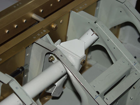
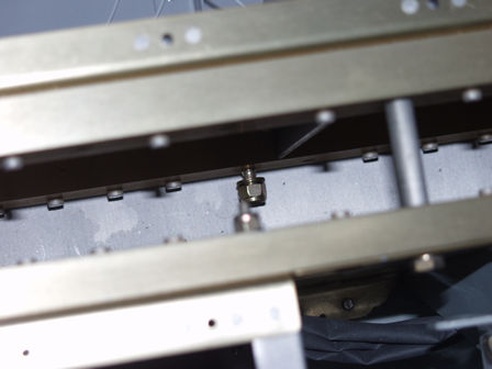
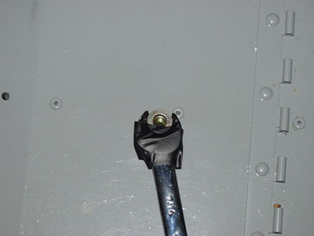
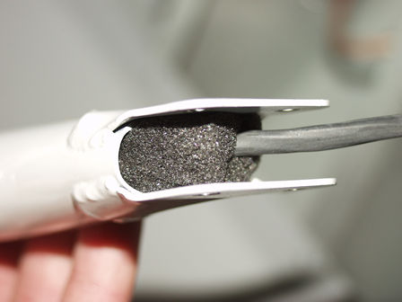
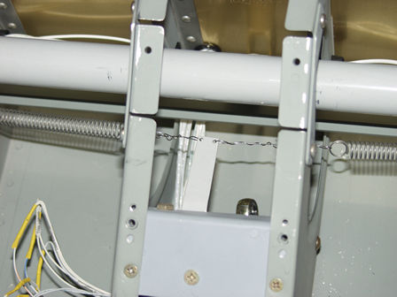
UPDATE: This later failed inspection as my inspector wanted the stainless steal wire to be a higher gauge. He also wanted it wrapped and looped more throught the trim arm.

To set the spring tension. Place one control fully over. Power the trim control to that side. Attach the spring with a very small amount of tension. Only a little. Repeat for the other side.

While in the back I torqued these control bolts.
While I was getting the parts for the aileron trim out I found the blanking screw for the fuel injection distributer. The additional hole is for a fuel pressure meter. I will be measuring my fuel pressure from the mechanical fuel pump, so it will show pressure available to the engine rather than pressure in the injection lines. This will show the mechanical and electrical pumps are functioning correctly. If pressure were lost in the injection lines you would soon hear a rough engine.

Images & text copyright GAPilot & Go-7. This mail is not connected to Vans Aircraft Inc. The contents of this site is the opinion of the author, not Vans Aircarft, PFA, CAA or FAA. Please check all information is correct before you act upon it.