

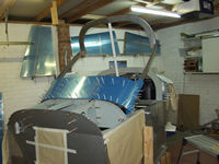
Fitting an Advanced AF-2500 Engine Monitor to Vans
RV7.
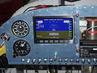
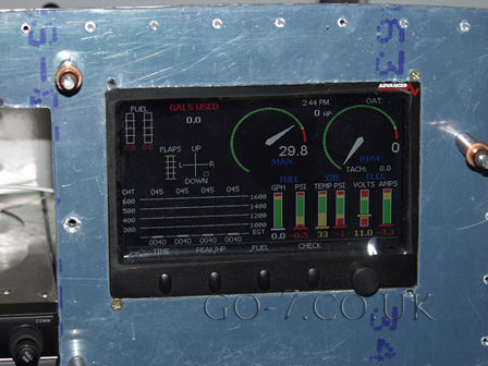
The Advanced AF-2500 monitors all the engine parameters
- Manifold Pressure, RPM, Oil Pressure Oil Temperature, Fuel Pressure,
Fuel flow, fuel tank levels (in flight and on the ground for tail
wheel a/c), Amps, Voltage, EGT & CHT on all 4 cylinders (also
available for 6)and some other aircarft parameters - Flap position,
Trim positions and user configured.
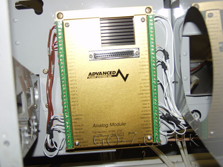
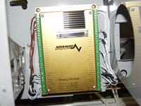
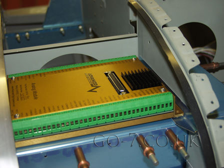
This is the Advance Analogue Module.
This is where all the sensors are connected to. I have sited this on the instrument sub panel. Some other builders have sided this module
behind the subpanel but I think this makes it difficult to maintain.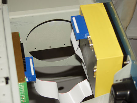
THE YELLOW tape around the digital unit is to cover the air vents during construction/building.
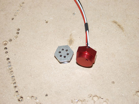
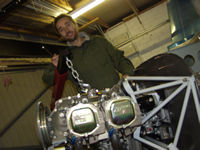
The RPM sensor
The red part is the sensor.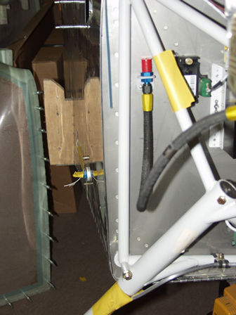
Manifod Pressure Sensor
I have fitted the manifold pressure sensor on the firewall.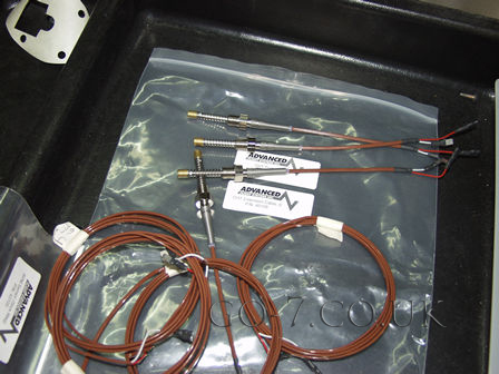
CHT Sensors.
The CHT sensors screw into the underside of the cylinder heads.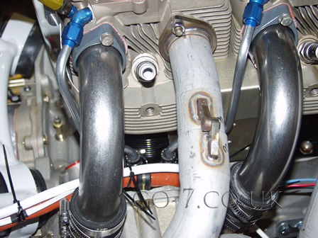
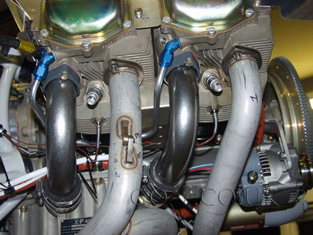
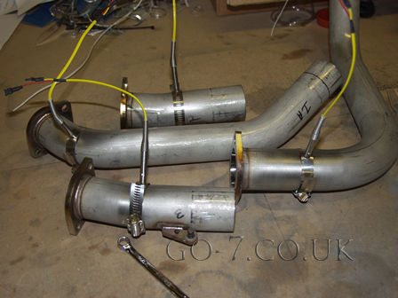
EGT Sensors
The EGT sensors fitted to the exhaust - see manual for distance/position.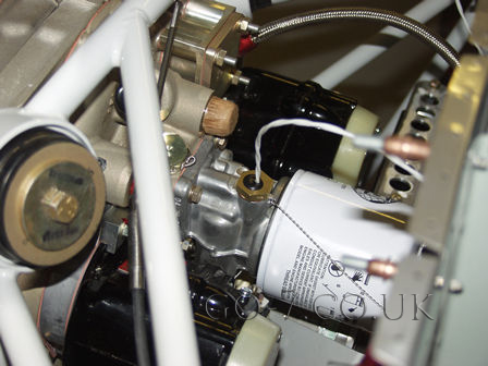
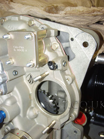
Oil Temp Sensor
You need to remove a blank and fit the oil temp sensor near the oil filter. It shoild be wire locked in place.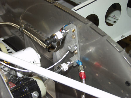
Oil and fuel pressure sensors
The oil and fuel pressure sensors are mounter remotly - via restrictor valves. The Vans manual suggests one part
of the remote sensor block is removed but I fould the two outer parts of the block posioned the sensors and remote pipes
better.
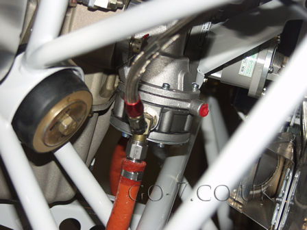
Fuel Pressure Sensor T and restrictor valve
The fuel pressure sensor is T'ed off from the out side of the manual fuel pump. I am sensing the fuel pressure after the manual put as
this will show the function of the mechanical pump. It will also show up the electrical fuel pump pressure changes.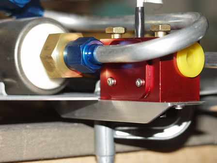
Fuel Flow Sensor
The fuel flow sensor is located in the fuse just after the electrical fuel
pump. There should not be any bends in the pipe or angles jounts etc
within 5 inches (sorry US imperial measurements) of the sensor.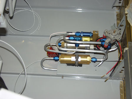
Fuel Flow Sensor (with injection high pressure fuel
pump)
The fuel flow sensor should not be in the high point of the sensor.