
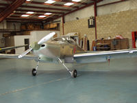
Wings on about to roll out of the
hanger for first engine start.
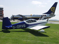
Roberts RV6, we stop for fuel on
the way to the RV fly-in at Colmar.
The way to fit split pins properly -
Aviation Standards!!

First Test flight of G-OVII my RV7 carried out by Bob Cole at Thruxton
on 18th November 2006.
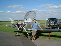
Here I am having just completed the first engine run.
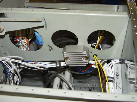
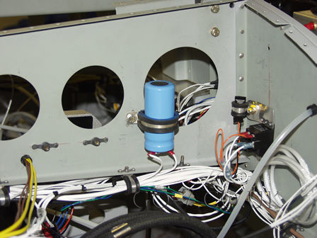
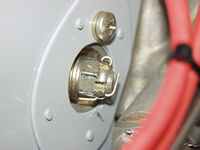
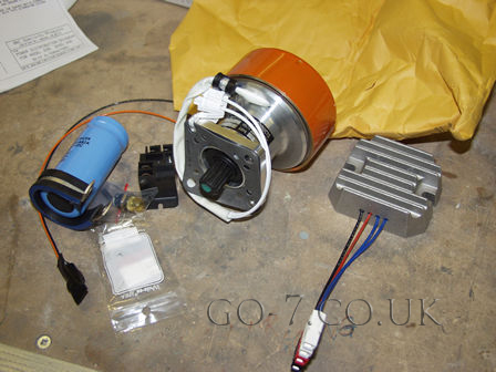
I decide to fit the B&C Model SD-8 alternator. It is a spline-driven 14V alternator that fits to the vacuum pump drive pad. I have to say I have been rather disappointed with the 'system'. Some of this disapointment is the way it has been marketed. A popular website that advocates keeping your electrical system simply praises this 'system,' however, I have found the 'system' of a dynamo, regulator, over volt circuit, capacitor and relay etc has all the potential for problems. Especially with all the connections and joints etc.
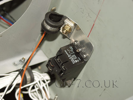
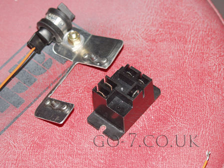
The accessory drive I am informed rotates at 1.5 times the engine
speed. See below for the output:
Engine RPM - Alt RPM - Current
2000rpm - 3000rpm - 6.8amps
2300rpm - 3450rpm - 4.3amps
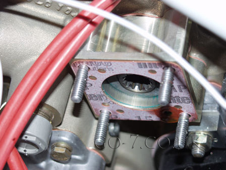
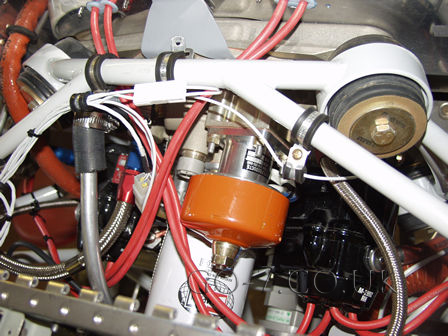
Another gripe - it would have been handy to know that the orange/red part of the alternator spins around!!