Heading www.gapilot.co.uk

Home Page

Construction Index

Build Diary 2004

Build Diary 2005

Build Diary 2006

Tools Required to build


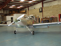
Wings on about to roll out of the
hanger for first engine start.


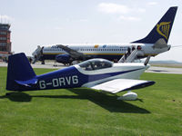
Roberts RV6, we stop for fuel on
the way to the RV fly-in at Colmar.


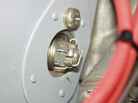
The way to fit split pins properly -
Aviation Standards!!

Test Flight with Bob Cole at the controls
First Test flight of G-OVII my RV7 carried out by Bob Cole at Thruxton on 18th November 2006.


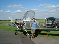
Here I am having just completed the first engine run.

Fitting Precision High Pressure (Fuel Injection) Fuel Pump to the RV7.

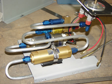
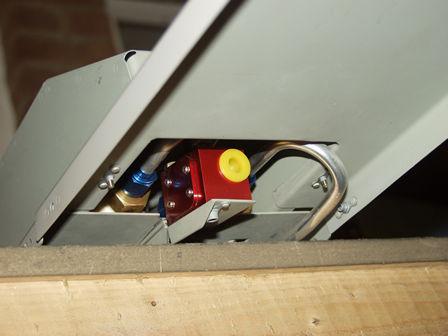
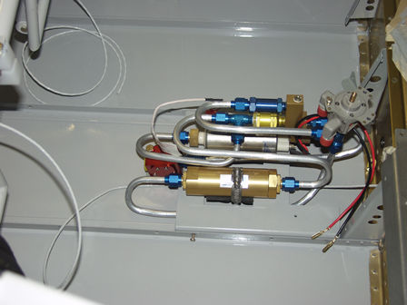
If you are fitting fuel injection to your engine you can use the Precision high pressure fuel pump and filter. This is available from Vans as a kit.
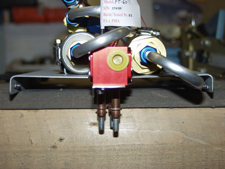
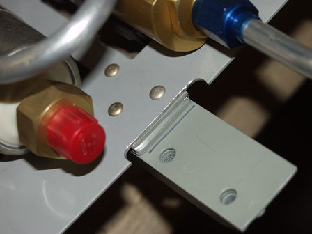
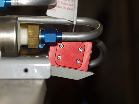
Here are some pictures of the pipes you need to bend - they may help you make sense of the Vans instructions and plans.
NOTE: I have added to fuel flow for my Advanced engine monitor - so the bends are NOT exactly as the Vans plans to allow the flow meter between the filter and pump.


The pump/filter kit as supplied by Vans. One pipe is fitted. When fitted to the FP/Filter plate the pump sits over slightly to one side. Some builders have modified the pump to sit upright.
Some builders have modified the pump to sit upright. I have not as it clears the cover.
OK, here we have the first bend. How many bits of pipe did the kit come with? How many have you now used!! So next order get some more pipe..... Seriously, don't bother trying to form the pipe by hand, a cheap pipe bender (see tools section) will do the job and you will not have any kinks.
I recommend putting the pump in place and the fuel tap to do the top bend otherwise you will struggle later fitting the tap and pump.
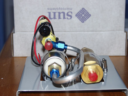
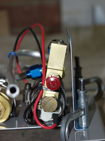
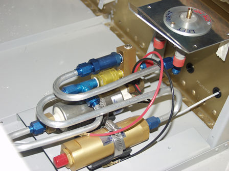
I am using the andair fuel tap - it's far better than the Vans kit supplied tap (but still available from the Vans catalogue!).


The fuel filter IN pipe. This is where I differ slightly from the Vans plans as I have the pipe bend to the side rather than center of the FP/Filter base plate. This is to make room for the fuel flow meter. the other end of the pipe goes to the fuel tap. The fuel is coming from the tap through the filter, but if it becomes blocked. It can go direct to the fuel pump.
The flow meter is now in place, and you can see the other end of the pipe fitted.
I have angled the flow meter down - later show in pictures below - but this show the position of front pipes.
The flow meter nounting point - I have also angled it down to avoid any bends in the pipe. The pipe should be straight for 5inches both sides of the meter.
The flow meter is angled down to avoid cutting the cover or running the pipe above the cover.


The flow meter with fuel pump cover fitted and center floor cover.
Finished fuel pump assembly. The pipes need fitting from the fuel tanks to fuel tap.